February 4, 2026 New Web Gauges
All Wi-Fi and Ethernet products have been updated: NMEA 2000 Wi-Fi Gateway YDWG-02, NMEA 2000 Wi-Fi Router YDNR-02, Ethernet Gateway YDEN-02, NMEA 0183 Wi-Fi Gateway YDWN-02, and NMEA 0183 Wi-Fi Router YDWR-02.
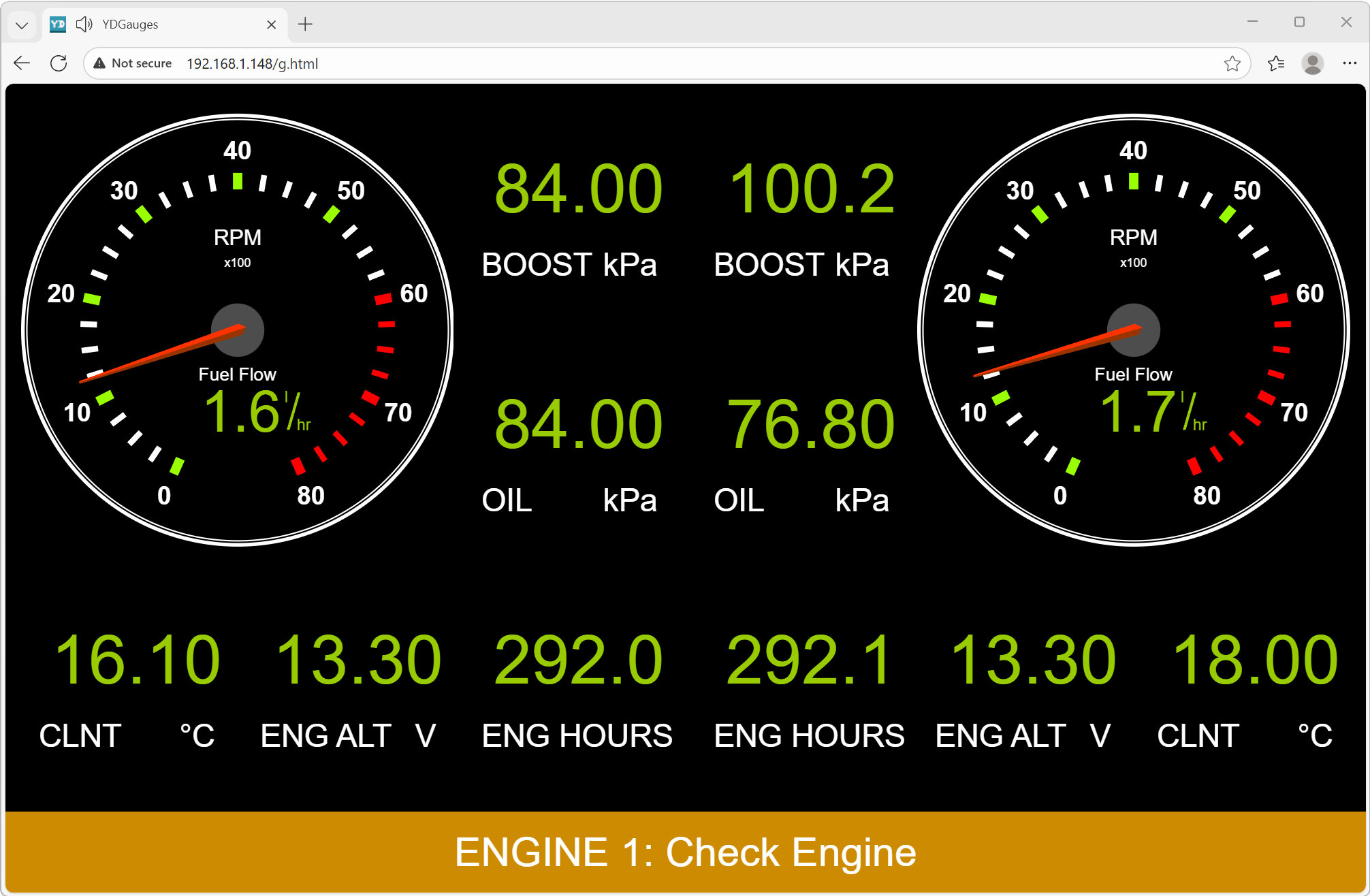
Today, Web Gauges allow you to monitor vessel data, manage digital loads and autopilot from any mobile device. It is a very convenient, powerful and flexible tool that works equally well on computers and mobile devices, on iOS, Android, Windows, Linux, Mac OS and any other operating systems with a modern browser.
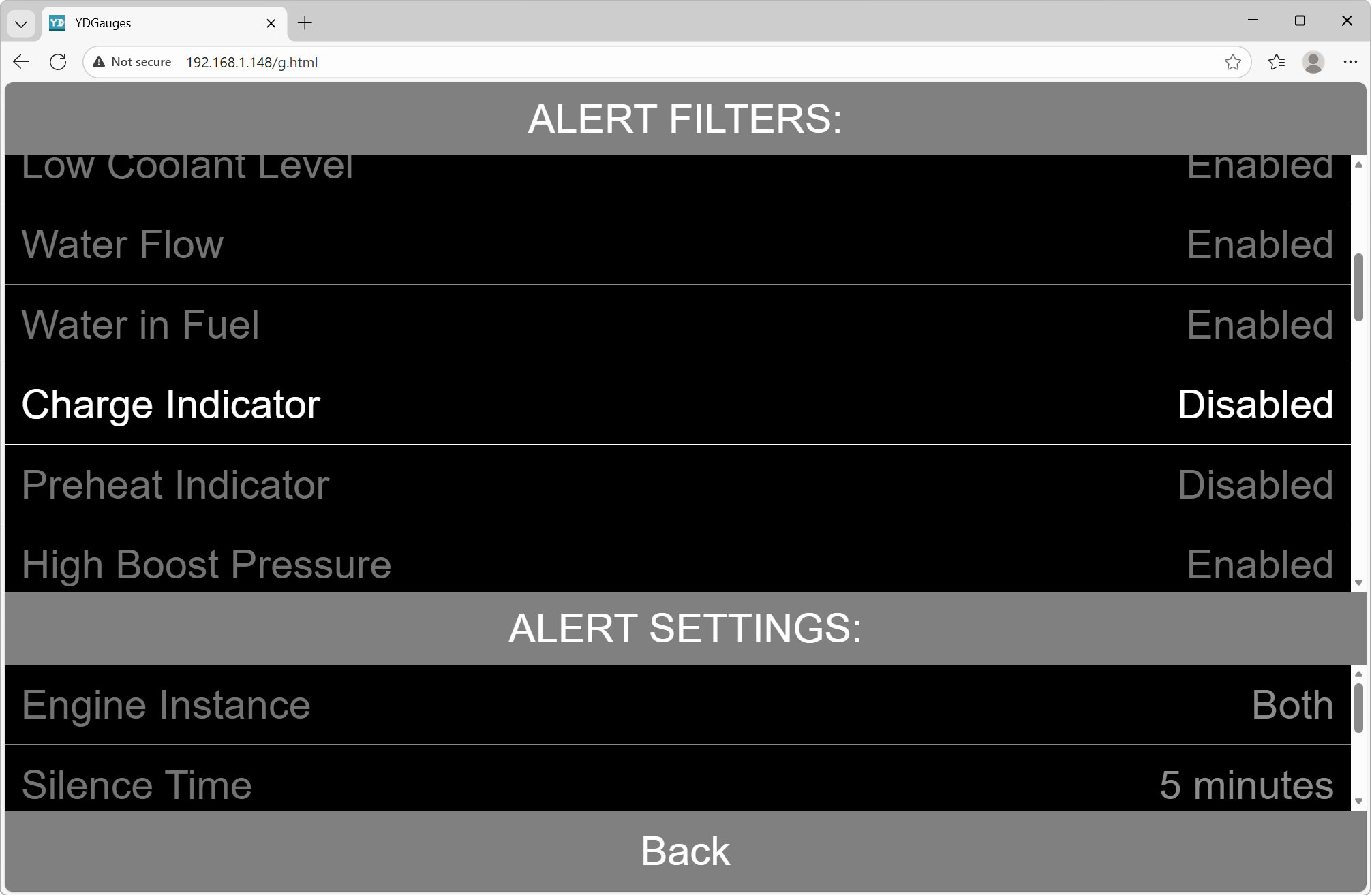
Engine data display was added several years ago, but only engine warnings were not available to users. The new version not only supports all engine and transmission errors and warnings, but also allows you to mute any of them. Moreover, pre-heating and charge notifications are disabled by default in the settings. You can also disable the sound alarm in the settings of Web Gauges, leaving only the text notification.
We have also added additional units of measurement for various quantities (we couldn't imagine that anyone would need kilometers per hour and millimeters of mercury) and improved the display of some data.
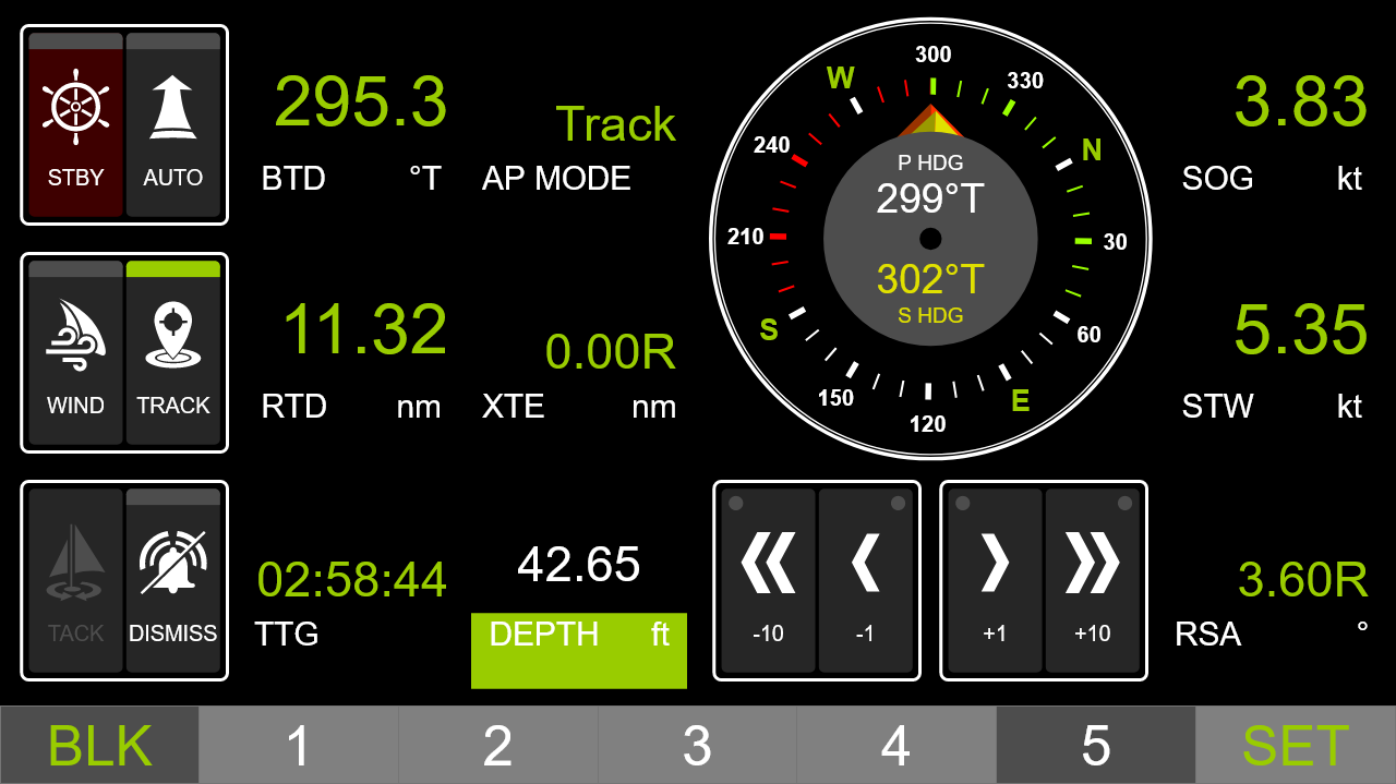
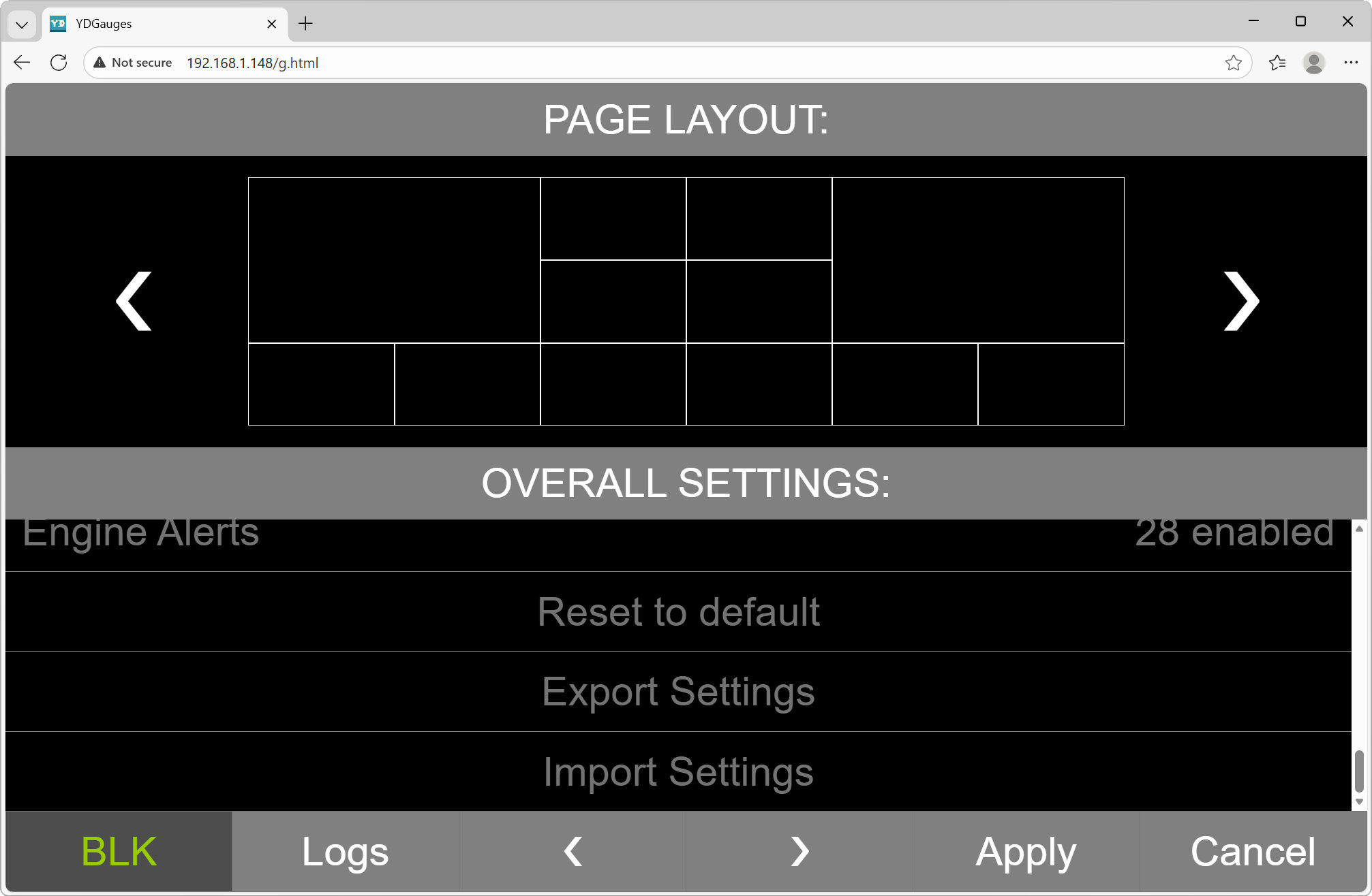
All these settings, as well as widget settings and data screen layouts, are stored in a special web browser storage and are linked to a specific browser on a specific user device. At the same time, Web Gauges have become so functional (just look at the default autopilot control page) that configuring them can take a lot of time. Now, import and export of settings has been added, which will allow you to easily transfer them between different browsers and devices and perform backups.
Bugs have also been fixed in the new firmware. For example, a bug in the implementation of web sockets in Ethernet Gateway has been fixed, which caused Web Gauges to work not stable with the new version of Apple Safari. In NMEA 2000 Wi-Fi Router and NMEA 0183 Wi-Fi Router, a bug in the conversion of longitude in one of the SeaTalk1 datagrams has been fixed. Important fixes have been made to devices with Yacht Devices Cloud support.
The new firmware with the same version 1.77 is already available at Downloads page for NMEA 2000 Wi-Fi Gateway, NMEA 2000 Wi-Fi Router, NMEA 0183 Wi-Fi Gateway, NMEA 0183 Wi-Fi Router and Ethernet Gateway.
January 19, 2026 Visit Our Partner Busse Yachtshop at Boot Dusseldorf 2026
We are pleased to inform you that our products will be represented at Boot Dusseldorf 2026 by our official partner Busse Yachtshop.
Busse Yachtshop has been one of our largest and longest-established partners for many years and has extensive hands-on experience with our products across a wide range of marine applications.
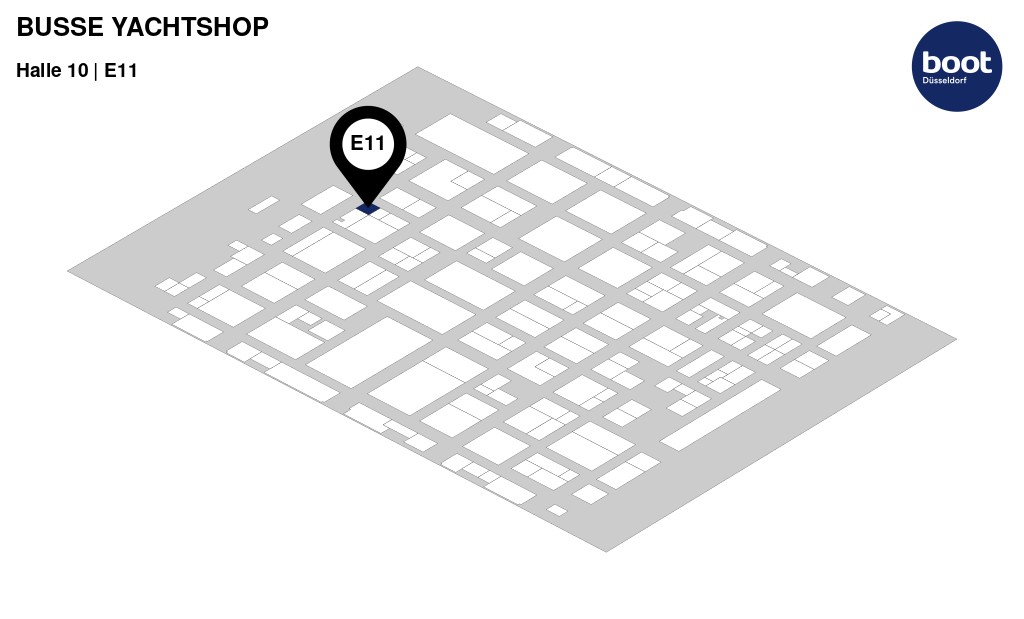
Visitors are welcome to meet the Busse Yachtshop team in Hall 10, Booth E11, where they can receive professional assistance, learn more about our product range, and discuss practical use cases directly with an experienced dealer who knows our solutions in depth.
Boot Dusseldorf, the world's leading trade fair for boating and water sports, runs until 25 January 2026.
Busse Yachtshop Team looking forward to welcoming you at the exhibition in Hall 10, Booth E11.
December 23, 2025 Merry Christmas and Happy New Year
We would like to congratulate you on the upcoming holidays and inform you that our holiday break will run from December 30 through January 4 inclusive.

Dear friends, our office will be closed from December 30 to January 4 inclusive. All inquiries and orders will be processed on Monday, January 5. Please bear with us - we will be back refreshed and full of energy!
This past year marked our 10th anniversary. It has been ten wonderful years of the best business in the world. We still feel a thrill when we imagine that somewhere right now, on the other side of the globe, one of our devices is conquering the ocean and blinking its green light - and, as usual, we envy it just a little.
This year we finally realized that we have grown up. The main challenges we faced included changes in customs regulations and duties, logistics between five warehouses in different countries, manufacturing injection molds, and fighting for deadlines and quality across two production facilities. There is probably no way to grow up without encountering all these boring adult things.
Not everything went exactly as planned. Due to logistics issues and production delays, we did not release the new line of sensors or the new Ethernet Gateway YDEN-03, which were presented in Dusseldorf at the exhibition in January this year. Nevertheless, the wait will not be much longer!
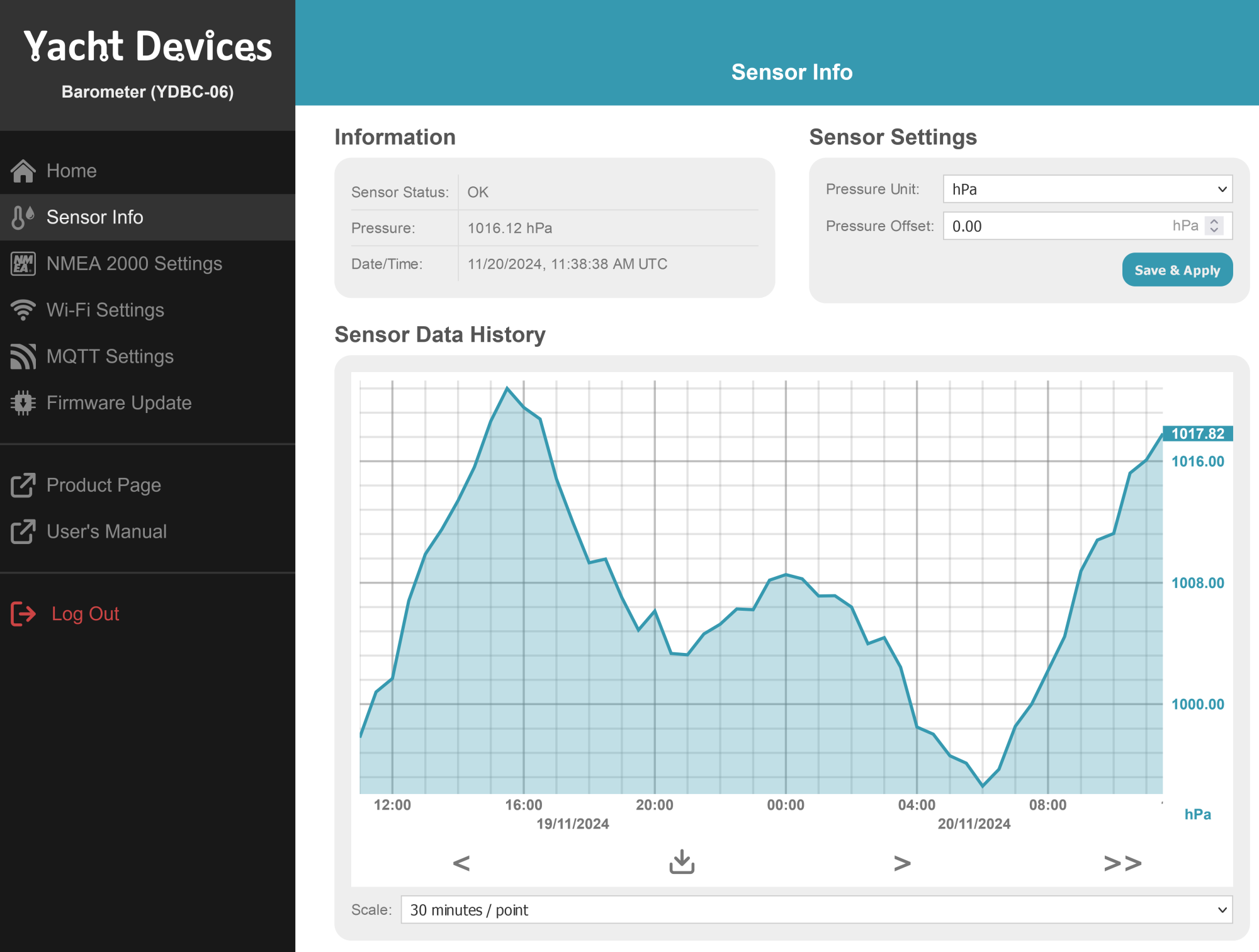
The new sensors feature Wi-Fi (which can be disabled) and make it easy to configure sensors, view measurement history (Barometer YDBC-06 becomes a real barograph, see above!), and integrate with smart homes or smart boats - all while maintaining the same dimensions and the same power consumption.
This year we also invested a lot of effort into our Autopilot. It no longer requires a rudder position sensor! This not only reduces installation cost but also allows it to be used on boats with outboard engines. The new model will also include Wi-Fi, enabling button-free control and easy configuration for different cruising conditions.
After equipping several small boats, we discovered that our devices are in high demand even on vessels as short as five meters, and we recorded a short video about it.
This year we updated the software of nearly all our products, making them better and better. Among other improvements, we added three new protocols to the Engine Gateway YDEG-04: for Suzuki outboard engines, Hyundai SeasAll inboard marine engines - and even Harley-Davidson motorcycles!
Now it's not only Tesla that can boast a huge touchscreen display. We installed a Raymarine Axiom on a motorcycle and made a fun video about it.
We wish you a joyful holiday season and hope you celebrate happily with your family and friends. Dream big, make bold plans, and bring your dreams to life!
Happy sailing in 2026!
Next articles:
- Harley-Davidson Support / December 10, 2025
- Suzuki and Hyundai protocols / October 23, 2025
- Latching buttons support / September 11, 2025